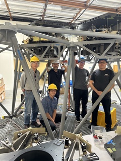
TMT Controls Team working on the sensor dust boots at the Multi Segment Integration & Test facility at Monrovia Lab, June 2023. From left to right: Mark Colavita (JPL), Takashi Nakamoto (TMT), Chris Carter (TMT), Jimmy Johnson (TMT), Andy Yeremian (Rebuild) with Justin Orr (Rebuild) not pictured. Image credit: TMT International Observatory
Dust Boot Design for TMT’s Primary Mirror Moves Into Final Design Stage
An important component of TMT’s Primary Mirror Control Sensing System and the Alignment and Phasing System is progressing to its final design and qualification stage: the sensor dust boots.
With 492 individual mirrors comprising the 30 meter diameter mirror, TMT’s primary mirror has a total of 2,772 edge sensors. Each side of each hexagonal segment has two edge sensors that pair with their facing sensors on the adjacent segment. Each pair consists of a drive side and a sense side that face each other across the gap between neighboring segments. The edge sensors are used to measure the relative positions of each of the M1 mirror segments.
TMT M1CS Edge Sensors (Drive and Sense pair) - TMT edge sensors will align and stabilize the relative out-of-plane degrees of freedom (piston, tip, and tilt) of each of the 492 hexagonal mirror segment that form the 30 meter TMT primary mirror. Image credit: TMT International Observatory
The drive side has two electrodes, each driven with AC voltages in the 50–100 kHz range. These two sensors couple capacitively across an ~5mm gap to a single electrode on the sense side. The gap between mirror segments is 2.5 mm. Demodulating the AC signals in firmware produces two 32-bit integer data products:
- A height output that can be further processed to give relative piston and the angle between the neighboring segments.
- A gap output that can be further processed to give the gap between the segments.
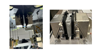
TMT M1CS Sensors Dust boot with sea. The sensor dust boots are designed to keep the sensors clean and dry. Functionality of the sensors dust boots is verified on the segments mounted on the Multi Segment Integration & Test facility at TMT lab. Image credit: TMT International Observatory
The performance of the capacitive sensors can be adversely affected by humidity. For this reason, each sensor pair is enclosed in a dust boot. Each boot is sealed and has a flow of clean air supplied to it, providing a clean and humidity-controlled environment. Each side of the boot holds both a sensor and the sensor analog electronics. The two halves of the dust boot are coupled together using a removable Carbothane seal. The dust boots are not allowed to impart forces across the intra-segment gap that affect the reading of the edge sensor over its performance range.
The design of the dust boot has been challenging and has taken many iterations to meet the stringent requirements. The adopted solution must not deteriorate the mirror seeing. There are specific weight requirements, and the solution must maintain the local environment in the sensor boot at less than 10% relative humidity, at all zenith angles, and over the sensor performance and component functional range. In addition, the system must maintain the stability of the cleanliness of the drive and sense surfaces to CL200 levels at all zenith angles, over the sensor performance and functional ranges while being subject to weekly CO2 snow cleaning (during the 492 mirror segments cleaning). The boot design must also minimize the pickup of magnetic interference.
The time required during segment removal and installation to mate/demate boot components, including seals and covers, and to clean blocks and boots, needs to be two minutes or less, with a goal of less than one minute.
“Working with Rebuild in Pasadena (formerly The Pilot Group) the dust boot design has now evolved to the point that we can move into the final design and qualification stage,” said Jimmy Johnson, Telescope Controls Group Leader. “This transitions us from 3D printed prototypes to injection molded parts. The solution that has evolved has the advantage that in addition to meeting all requirements, passing CO2 cleaning and dust attenuation tests and mate/demate operations on the Multi Segment Integration & Test facility at Monrovia, it does not require any special tooling, and seals can be installed and removed entirely by hand."