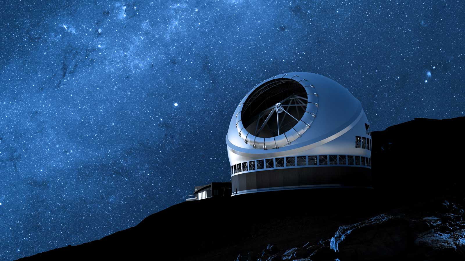
NFIRAOS on the telescope and with instruments attached
NFIRAOS optical enclosure with IRIS and conceptual MODHIS instruments attached
The first light Adaptive Optics (AO) architecture for TMT has been designed to provide diffraction-limited wavefront quality and high sky coverage in the near infrared (IR) for the first TMT science instruments IRIS and MODHIS. Design, prototyping and fabrication activities of the TMT first light AO subsystems and their components are underway in Canada, France and the US. NFIRAOS is an order 60 x 60 laser guide star (LGS) multi-conjugate AO (MCAO) system, which provides uniform, diffraction-limited performance in the J, H, and K bands over 34 x 34 arc sec fields with 50 per cent sky coverage at the galactic pole, as required to support the TMT science cases.
The first light AO architecture for TMT consists of the following major systems:
NFIRAOS optical layout
The TMT facility AO system, NFIRAOS, enables NGSAO, LGS MCAO and seeing-limited observing modes. Each of the NFIRAOS science instruments will provide up to three low order on‑instrument wavefront sensors (OIWFS) and (for IRIS only) multiple on-detector guide windows (ODGW) to provide high precision tip/tilt, and (only in the case of 2x2 mode) focus and astigmatism measurements. When running at high speed, the OIWFS or ODGW measurements are used for tip/tilt, focus and plate scale control. When running at low speed, they can compensate for flexure between NFIRAOS and the science instrument. The ODGW additional compensate for flexure of the OIWFS because they are directly located on the science focal plane.
NFIRAOS has three instrument output ports. An Instrument Selection Mirror (ISM) is used to feed light to any of these three ports. At first light, these three ports are expected to be occupied by 1) IRIS, an imager and integral field spectrograph, 2) MODHIS, a multi-fiber high resolution spectrograph with coronagraphic capabilities, and 3) NSEN, a non-science instrument that contains an acquisition camera (NSEN ACQ) and a diffraction-limited NIR camera.
NFIRAOS can be operated in three different modes:
In LGS MCAO mode, NFIRAOS uses six LGS wavefront sensors and the pyramid wave front sensor (PWFS) located within NFIRAOS, as well as up to three on-instrument wavefront sensors (OIWFS) and/or up to four on-detector guide windows (ODGW) provided by client instruments. The PWFS is used as a truth WFS (TWFS) running at low frame rate for correcting aberrations arising from changes in the sodium layer profile. The OIWFS are generally used to provide tip/tilt, focus and plate scale control. ODGW can be used as well if bright guide stars are available within the imager focal plane to provide tip/tilt measurements. If faint guide stars are available within the imager focal plane, the ODGW can be used as tip/tilt truth WFS running at lower speed, to provide flexure compensation between OIWFS and instrument focal plane. There are also cases when a fast TTF OIWFS measurement cannot be used due to reasons like 1) vignetting of the science target, 2) extended guide object that is comparable in size to the seeing or 3) lacking infrared guide stars. The PWFS may then be used instead to provide high speed but less accurate tip/tilt/focus control and the TTF OIWFS could be used as tip/tilt/focus truth WFS with a faint guide star while other TT OIWFS and/or ODGW may be used as tip/tilt truth WFS.
In NGSAO mode, NFIRAOS uses the PWFS with a bright visible natural guide star, and optionally a TTF OIWFS and/or an ODGW, to close the AO loops. The NGS is usually a star but can be a small extended object. The PWFS running in 96x96 mode has an effective sub-aperture size of 0.31 meters and a magnitude limit of R~13.5 (RD1) for an on axis H band Strehl ratio of 50%. With a bright NGS (R<11), the NGSAO mode will provide superior on-axis performance to that of LGS mode, but the performance will degrade for guide stars that are dimmer or at distances greater than about 5 arcsec from the science object.
For slit based configurations of potential future NFIRAOS client instruments, there will be science cases where NFIRAOS will be used as an active optics system in seeing-limited mode. This mode is implemented as degraded NGSAO mode with the PWFS binned down and operating at a lower frame rate with an optional TTF OIWFS in the instrument.
In order to make efficient use of TMT, NFIRAOS and the science instruments, observers will need to prepare their observations in advance. To make these preparations, observers will need access to guide star catalogues and observation preparation software tools, including integration time calculators and AO performance modeling tools.
The Strehl ratio delivered by NFIRAOS will depend most critically on the seeing at the time of the observation. However, other factors may also have a significant impact on the system performance. These factors include air-mass, sky transparency and background (moon phase), brightness and locations of natural guide stars, etc. There may also be other tradeoffs to be made; for example, is the system better with a mildly extended tip‑tilt source close to the science target or using a point source that is located at the outermost limits of the tip-tilt guide field?
To properly identify the observing conditions that are required for a successful NFIRAOS observation, and make informed decisions regarding guide stars, the observer will use the OIWFS selection tool (as part of OSW), which includes the NFIRAOS AO performance modeling tool, to select the optimal OIWFS guide asterism ahead of the observation using known star catalogue information or available images. If the selected guide stars have not been used before, backup stars should also be selected in case the stars are not point sources or have incorrect magnitudes. TMT will keep a database for guide stars that have been successfully used.
The OIWFS selection tool can also be used during the acquisition step with acquisition images taken by the NFIRAOS acquisition camera or science instruments. The OIWFS selection tool should be able to select a near optimal asterism in less than 10 seconds.
Observing programs will need to provide the following inputs for the successful execution of the observations:
These inputs will need to be provided by observers in a format that can be stored in the observing database so that observing programs can be efficiently sequenced. Sequencing will be key to meeting the required acquisition time budgets.
For AO observations, a backup plan should always be prepared in case:
The backup plan should ideally include NGSAO mode and seeing limited mode operations. Backup science targets may also be prepared, e.g. standard stars. Detailed parameters should be provided for each AO mode in the backup plan.
Ideally it would be possible to employ adaptive optics at any desired location on the sky. In practice the sky coverage is limited by the availability of suitable natural guide stars. TMT will be able to access almost the entire sky because the large aperture means that faint natural guide stars can be utilized. Detailed modeling of the performance of the NFIRAOS first light adaptive optics system has been carried out for all positions on the sky accessible by TMT (i.e. for zenith angles less than 65o) and for all observing conditions (i.e. a full range of atmospheric turbulence profiles). NFIRAOS is designed to provide excellent corrections over J, H and K bands. J band, the shortest wavelengths, will be the most challenging.
J band Strehl ratio map for the median availability of guide stars for fields crossing the meridian. This is for 75th percentile seeing conditions (worse than average).
J band Strehl ratio map for the median availability of guide stars for fields crossing the meridian. This is for median seeing conditions.
J band Strehl ratio map for the median availability of guide stars for fields crossing the meridian. This is for 25th percentile seeing conditions (better than average).
To fully realize the scientific potential of diffraction-limited AO-corrected science observations, detailed knowledge of the point-spread function is needed. TMT ultimately aims to deliver PSFs reconstructed from AO telemetry for all AO systems, and significant algorithm development has already taken place (Gilles et al. 2018).
Power: 20-25 W per LGS
Wavelength: 589 nm
LGS Spot Size: The laser spot size at the sodium layer location (between 90 and 235 km) to be less than 0.8 arcsec for short exposure during median seeing conditions.
Beam Stability on the Sky: To be better than 50 mas RMS.
Polarization: The laser beams are converted from linear to circular polarization before projecting to sky with ellipticity better than 1.02.
Uplink Throughput: 75% or better.
Pointing: The LGSF global pointing accuracy shall be better than +/-1 arcsec peak-to-valley on the sky relative to the telescope line-of-sight.
Operation downtime: The LGSF unscheduled downtime not to exceed 5.7 hours each year (corresponds to 0.19% maximum downtime; using 3,000 hrs of operation per year).
Laser Guide Star Facility on the telescope
The LGSF is responsible for generating artificial guide stars in the mesospheric sodium layer with the brightness, beam quality and asterism geometries required by both the NFIRAOS early light AO system and later AO instruments.
The baseline LGSF consists of 3 primary sub-systems:
LGSF mechanical decomposition
LGSF Optical Layout
The LGSF optical layout shows the LGSF Laser Units and the LGSF BTO locations on the telescope and the different components and mechanisms of the design. The LGSF Beam Transfer Optics use conventional optics as opposed to fibers to transport, format and launch the LGS asterisms from behind the TMT secondary mirror.
The lasers beams are generated by the Laser Heads (LHs) mounted on the -X elevation journal (bottom of the optical layout figure). Below each Laser Head, a Laser Bench (LB) is installed to format and fold the laser beam along the optical path. The laser beams are first expanded via a relay lens (one per beam), and then folded to form an array of 3x3 beams (without the center beam) along the laser platform, and then transported up to the telescope Top End via a set of active and non-active fold mirrors. These fold mirrors are either simple mirrors or arrays of mirrors.
Once the beams reach the top end, they are directed via a set of arrays to the Asterism Generator Main assembly, which converts the 3x3 pattern into the required LGS asterism. The asterism is then expanded and launched to the sky via the Collimator and the Laser Launch Telescope (LLT). Before entering the LLT, the laser beams are de-rotated using the K-Mirror to provide a fixed asterism in the AO system LGS wavefront sensor focal planes.
Laser beam polarization is optimized to maximize the photon return of the corresponding LGS via a couple of Quarter Wave Plates located on each Laser Bench. Telescope flexure is controlled by actuating in tip/tilt the different fold mirrors and arrays along the BTO Optical Path, on the BTO Top End, and within the LLT. Additionally, the entire LLT is mounted on a pivot mount to compensate for large telescope flexure around the X axis. The Pre-Alignment Cameras (PAC) within the BTO Optical Path and BTO Top End are used for measuring the beam positions, which in turn are used to control the telescope flexure either via Look Up Tables (LUT) or via slow real time control of the actuated mirrors or arrays.
The Asterism Generator includes the Fast Steering Mirrors which use the inputs from the AO System to compensate for up-link turbulence and windshake. The Laser Launch Telescope also includes two medium bandwidth steering mirrors to compensate for telescope flexure along the Y axis and turbulence or tip-tilt induced vibration.
Finally, the LGSF BTO Top End is equipped with a slow shutter (Beam Dump Mirror) which directs most of the laser light to a beam dump, but also allows to measure the beam pointing, centering and wavefront error using a Shack Hartman WFS as well as polarization using a polarization meter. The Acquisition Telescope and associated camera allows to check that the asterisms are generated with the proper geometry and location onto the sky.
The Aircraft Detection System is part of the LGSF Safety System and is used to detect aircrafts in the vicinity of the laser beams; upon detection, the laser beams are shuttered.
Geometric distribution of the LGSF guide stars
The LGSF will provide several asterism configuration available for different operation modes: