The Thirty Meter Telescope is shown at a very low elevation angle. The segmented primary mirror reflects the convex secondary mirror. The tertiary mirror in the center of the primary mirror is oriented to send light to the Wide Field Optical Spectrograph, the gray structure located on the right side of the image. The left and right instrument platforms are seen and the dark blue adaptive optics enclosure is seen on the upper left on the instrument support structure.
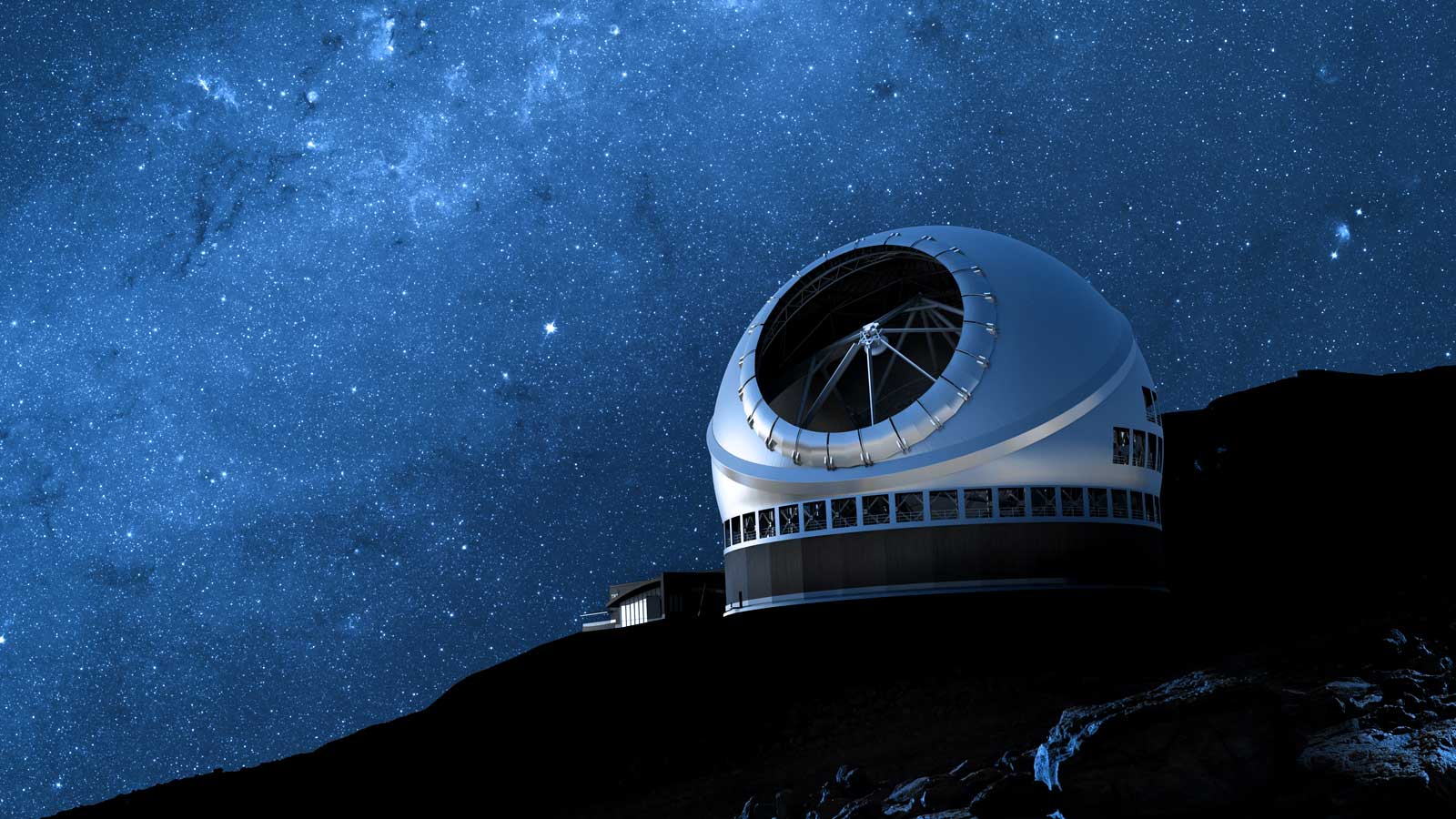
Artist rendering of the completed Thirty Meter Telescope during nighttime deploying lasers for Adaptive Optics towards the Northern Milky Way.
TMT Segment Support Assemblies (SSA) are opto-mechanical systems that provide the support for each individual piece of mirror segment. During transport and storage within their container, SSAs are entirely wrapped in a zipped closed Intercept fabric bag for protecting the delicate electronic features from moisture and corrosive environment. Data loggers are mounted into the container and on the SSA to monitor and collect information on shock amplitude, temperature and humidity.
Screenshot of the participants from ITCC, L&T, TMT Optics, Systems Engineering & Quality Assurance teams participating in the review held remotely on 11th & 12th April, 2023.
Larsen & Toubro (L&T) and TMT-Project Office (TMTPO) participants at the Segment Support Assembly (SSA) flagg off event meeting at L&T facility, Coimbatore, in India – March 2023. Nikhil Naik, TMT Production Support Engineer; P Rajkumar, L&T Precision Manufacturing and Systems Complex, Coimbatore Unit Head; Karthic Kumar, SSA Work Package Manager at the India TMT Coordination Center (ITCC) and Eswar Reddy, ITCC Programme Director (respectively 6th, 5th, 4th and 3rd from the right) along with L&T and ITCC engineers and production team in the dedicated room for TMT SSA assembly work at L&T facility in Coimbatore, India.
From left: Dhiyanesh, Project Manager at Larsen and Toubro (L&T) industry partner; Nikhil Naik, TMT Production Support Engineer; Karthic Kumar, SSA Work Package Manager at the India TMT Coordination Center (ITCC); Selva Kumar, Assistant Manager - Quality at L&T and Ananthu C M, QA Engineer at ITCC. The TMT’s Segment Support Assemblies (SSA) seen in the picture were manufactured and assembled by L&T.
The first five TMT Segment Support Assembly (SSA) sets were manufactured and assembled at Larsen and Toubro (L&T) Coimbatore facility prior to be shipped to India’s TMT Optical Fabrication Facility (ITOFF).
TMT Segment Support Assemblies (SSA) are opto-mechanical systems that provide the support for each individual piece of mirror segment.
In March 2023, five TMT Segment Support Assemblies (SSA) were completed in Coimbatore, India, by the Larsen and Toubro (L&T) company. On the first row are Nikhil Naik, TMT Production Support Engineer, Karthic Kumar, SSA Work Package Manager at the India TMT Coordination Center (ITCC) and Eswar Reddy, ITCC Programme Director (respectively 8th, 5th and 7th from the left) posing with the L&T SSA production team and members of the ITCC group to commemorate the first five sets of SSA shipped to India’s TMT optics fabrication facility.
The Thirty Meter Telescope is shown at a very low elevation angle. The segmented primary mirror reflects the convex secondary mirror. The tertiary mirror in the center of the primary mirror is oriented to send light to the Wide Field Optical Spectrograph, the gray structure located on the right side of the image. The left and right instrument platforms are seen and the dark blue adaptive optics enclosure is seen on the upper left on the instrument support structure.
Overview showing WFOIS instrument ...
The Thirty Meter Telescope is shown oriented straight up to the zenith viewed from behind the telescope tube, the telescope tips away to the back of the image to lower elevations. The segmented primary mirror reflects some of the segment handling system and the four mirror cleaning arms can be seen around the circumference of the primary mirror. The two instrument platforms are seen with the light blue adaptive optics enclosure on the platform on the right of the image. Attached to top of the adaptive optics system is the MODHIS instrument on top, shown in dark blue, the IRIS instrument beneath, seen as gray, and on the side port is a commissioning instrument, also shown as gray. The tertiary mirror in the center of the primary mirror is oriented to send light to the Wide Field Optical Spectrograph, the light gray structure located on the instrument platform on the left side of the image. The foreground structure is part of the mirror segment handling system that transfers segments up and down to the observatory floor and on and off the segment handling system above the primary mirror. Segment exchanges take place with the telescope oriented to the zenith.